DrawingML Shapes
A custom geometric shape consisting of most any series of lines and curves can be specified with a <a:custGeom> element. The most important component of a <a:custGeom> is the specification of the path that the shape takes. This is specified with a child <a:pathLst> element. But there are also other optional components of a custom shape that can be specified. The placement of shape adjustment handles can be specified with a child <a:ahLst> (not covered here). The location of connection points (locations on the object where lines or connectors can be placed) can be specified with a child <a:cxnLst>. A rectangular bounding box for text within the shape can be specified with a child <a:rect>. Finally, a shape's edges can be dynamically determined or adjusted based upon formulas rather than static placement. This is done using adjust values (<a:avLst>) and shape guides (<a:gdLst>). This aspect of custom geometry is not covered here.
Defining the shape's path
A shape is specified by one or more paths contained within a <a:pathLst> element. Each path is a set of moves, lines and arcs contained within a <a:path> child element. Essentially each path can be thought of as a separate shape. The end point of the previous path will be connected to the first point of the new path unless the previous path specifies a <a:close> element. Note that since multiple paths are allowed, later paths are drawn on top of previous paths.
A path has a space specified by the height (h) and width (w) attributes of the <a:path> element. The path is then specified with points (represented by <a:pt> elements) defined within the path's space using x-y coordinates. Note the coordinate system as shown in the image. 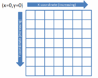 The <a:pt> has x and y attributes that define the coordinates of the point. Be sure not to confuse the shape coordinate system with the path coordinate system; they are distinct The shape coordinate system or the shape bounding box is defined by the <a:ext> within the <a:xfrm> element and is specified in EMUs. The path coordinate system is defined by the h and w attributes of the <a:path> element, which may not be in EMUs. Path points are defined in terms of the path coordinate system.
As mentioned above, a path is defined by drawing a sequence of lines (<a:lnTo>), arcs (<a:arcTo>), cubic bezier curves (<a:cubicBezTo>), and quadratic bezier curves (<a:quadBezTo>). The drawing of lines and curves can be interrupted by moving to a new coordinate and drawing from the new location; this is specified with <a:moveTo> element. Each of the elements just mentioned has one, two, or three <a:pt> child elements.
A <a:path> has the following elements.
| Element | Description |
|---|---|
| arcTo | An empty element that specifies an arc from the current pen position to the new point. An arc is a line that is bent based on the shape of a supposed circle. The length is determined by a start angle and an ending angle. The arcTo element has four possible attributes which define the arc: hR (the height radius in EMUs or a number immediately followed by a unit identifier), stAng (the start angle in 60,000ths of a degree; positive values are clockwise), swAng (the swing angle), and wR (the width radius). |
| close | An empty element that specifies the end of a series of lines and curves and signals to the application that that the path is closed and any further lines or curves should be ignored. When the last point does not meet the first point in the path, the application should connect the last point with the first with a straight line to create a closed shape. The <a:close> also means that the subsequent path (if any) will not be connected to the previous path. If a path is not closed, then the shape will have no fill. |
| cubicBezTo | Specifies to draw a cubic bezier curve along the specified points. There must be three child <a:pt> points specified. The first two are control points used in the cubic bezier calculation and last is the ending point. |
| lnTo | Specifies the drawing of a straight line. It contains one child <a:pt> element. |
| moveTo | Specifies a set of coordinates to move the shape cursor to. It does not draw a line or curve; it simply moves the cursor to a new position. It contains one child <a:pt> element. |
| quadBezTo | Specifies to draw a quadratic bezier curve along the specified points. There must be two child <a:pt> point elements. |
A <a:path> has the following attributes.
| Attribute | Description |
|---|---|
| extrusionOk | Specifies that 3D extrusions are allowed. If ommitted, it is assumed that the value is false. |
| fill | Specifies how the corresponding path should be filled. Possible values are darken, darkenLess, lighten, darkenLess, none, and normal (assumed if the attribute is omitted). See the sample of two paths below. The fill of the second path has been darkened. |
| h | Specifies the height or maximum y coordinate the should be used. It determines the vertical placement of all points in the path as they are all calculated using this attribute as the max y coordinate. |
| stroke | Specifies if the corresponding path should have a path stroke shown. If omitted, the value is assumed to be true. |
| w | Specifies the width or maximum z coordinate the should be used. It determines the horizontal placement of all points in the path as they are all calculated using this attribute as the max x coordinate. |
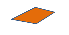
Below is a sample of a custom geometrical shape with one path. First the cursor is moved to new coordinates at (0,428263) as specified by the <a:moveTo> element. Then a series of three lines is drawn. In the example, a <a:close> element is specified to signal to the application that that the path is closed and any further lines or curves should be ignored. When the last point does not meet the first point in the path, the application should connect the last point with the first with a straight line to create a closed shape. The <a:close> also means that the subsequent path (if any) will not be connected to the previous path. If a path is not closed, then the shape will have no fill.
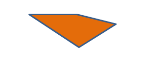
Below is the same shape, except that the initial <a:moveTo> has been removed, so that drawing begins at the origin point.
Below is another example of a custom shape. This time there are two paths. The first is the same as the first path shown above. It is closed, so that path and the subsequent path are not connected. The second path is darkened with the fill="darken" attribute. First the cursor is moved to (1000000,334000); the path then draws two lines. Then it moves again, this time to (500000,500000). Finally, it draws another line and closes.

Defining the shape's connection points
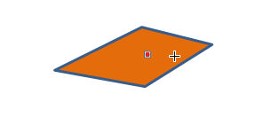
A shape can have connection sites where connectors can be attached so that the connections are maintained when the shape is repositioned. Each connection site is specified with a <a:cxn> element. All of the <a:cxn> elements are within a container <a:cxnLst> parent element. Each connection site is positioned with a child <a:pos> element, which specifies coordinates with its x and y attributes. It should be noted that the connection is placed within the bounding box using the shape coordinate system encompassing the entire shape, which is specified with the <a:ext> element. The <a:pos> element also has an ang attribute which specifies the incoming connector angle. This allows the connector to know where the shape is in relation to the connection site and route connectors so as to avoid placement over the shape. Below is a sample of a connection site located in the middle of the shape.
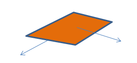
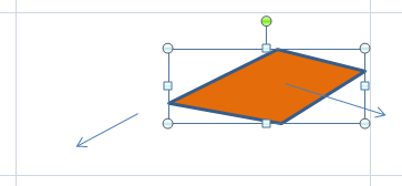
Below is an example of two connectors being attached -- one at the specified connection site in the middle of the shape and one that is not at a connection site. The image on the right is the same shape, but it has been repositioned. The connector at the connection site is maintained with the shape while the other connector has not been maintained.
Defining the shape's bounding box for text
By default text within a a custom shape is placed within the bounding box for the shape. However, this can be modified with the <a:rect> element, which has attributes to inset or extend the text bounding box. The attributes are b (y coordinate for the bottom edge), l (x coordinate for the left edge), r (x coordinate for the right edge), and t (y coordinate for the top edge).
